I 15 Road Plan and Profile Drawings
Plan/profile canvas
Last updated: 2020-10-26
Full video time: lxx:37
![]() Create view frame grouping file and information shortcut alignments
Create view frame grouping file and information shortcut alignments
File setup
- Create a sheet set for the project if one has not been created all the same. See Canvass sets for more information.
- Start a new drawing from design-start.dwt template
- Save file as ProjectID\Blueprint\ViewFrameGroups\VFG-51-pp-100scale.dwg
- View frames tin be saved in the design file for smaller projects
- For longer projects, the program and profile sheets may be separated into multiple drawings. This procedure keeps the view frames uniform throughout multiple drawings. A separate view frame group file does Non need to be created if your projection doesn't warrant it.
- Generally a 1IN:100FT scale is used for rural projects, 1IN:40FT or 1IN:50FT calibration is more ideal for urban projects
- Annotation scale: 1IN:100FT
- Data reference
- Toolspace palette > Prospector tab > Data Shortcuts > Centerline Alignments > 51 > Correct-click > Create Reference...
- OK
- Toolspace palette > Prospector tab > Information Shortcuts > Centerline Alignments > 51 > Profiles > 51 > Right-click > Create Reference...
-
OK
Tip: It is important to add the profile before the view frames are created. The view frames demand to "know" this information for later when the profile views are added to the layouts.
-
- Toolspace palette > Prospector tab > Information Shortcuts > Centerline Alignments > Lcl-Tuckaway Rd. > Correct-click > Create Reference...
- OK
- Toolspace palette > Prospector tab > Data Shortcuts > Centerline Alignments > 47 > Right-click > Create Reference...
- OK
- Toolspace palette > Prospector tab > Data Shortcuts > Centerline Alignments > 51 > Correct-click > Create Reference...
- Double-click the centre mouse wheel to zoom extents.
- Salvage the file.
![]() Create view frames and group i
Create view frames and group i
pln-prod-pln-prof-02.mp4 2:44
- Output tab > Plan Production panel > Create View Frames
- Create View Frames dialog box
- Alignment: 51
- Station Range: User Specified
- Offset station: 547+00
- End station: 606+00
- User specified starting time station should exist to the nearest +25/50/100 station earlier the construction limits. The end station should exist to the nearest +25/50/100 station across the construction limits.
- Station Range: User Specified
- Sheets
- Sheet Settings
- Sheet Type: Programme and Profile
- Template for Plan and Profile canvas
- ... > Cartoon template file name: C:\Wisdot\Stnd\C3D20XX\Templates\Sheets\05-PP-wdot.dwt
- Select the ellipse button for boosted sail templates
- Select a layout to create new sheets: PlanProf 1 IN 100FT
- OK
- ... > Cartoon template file name: C:\Wisdot\Stnd\C3D20XX\Templates\Sheets\05-PP-wdot.dwt
- View Frame Placement
- Ready the first view earlier the beginning of the alignment: Non checked
- If the view frames are not created in the desired locations, delete them and recreate the frames from an before beginning station. This option may exist used if needed.
- Ready the first view earlier the beginning of the alignment: Non checked
- Sheet Settings
- Alignment: 51
![]() Create view frames and group two
Create view frames and group two
pln-prod-pln-prof-03.mp4 three:twenty
- Output tab > Programme Product panel > Create View Frames (connected)
- View Frame Group
- View Frame Group > Name: VFG - 51-100-pp
- View Frame > Name: Click on Edit View frame Group name... icon
- Name
- Delete and clear out default name
- Property fields: dropdown > select Side by side Counter
- Insert
- Number style dropdown: 01, 02, 03...
- Starting number: one
- OK
- Name
- Match Lines
- Positioning
- Snap station value down to the nearest: checked
- Snap station value downwards to the nearest value: ten
- Friction match Line
- Style: Match Line (No Plot)
- match lines will display in the file and so their location is visible simply they will non plot
- Style: Match Line (No Plot)
- Labels
- Left label style: none
- Right label way: none
- Positioning
- Contour Views
- Profile View Mode
- Select contour view style dropdown: Stations 100'Major:50'Minor 1:10Vert Ex
- Ring Fix
- Select ring prepare manner dropdown: Tiptop Both (Existing Left Proposed Right)
- Profile View Mode
- Create View Frames
- View Frame Group
- Salve the file
![]() Edit view frame locations
Edit view frame locations
pln-prod-pln-prof-04.mp4 2:30
Review the view frame placement along the alignment.
Tip: Whatsoever view frame location changes should be fabricated before profile views are fabricated and sheets are created. Sheets are non updated if the view frames are moved after the sheets have been created, this is a one fourth dimension performance.
There are multiple options for adjusting the view frames to the desired location before the sheets are created.
Option ane - Shifting all the view frames
If the view frames are non created in the desired locations, delete them and recreate the frames from an earlier commencement station.
- Output tab > Plan Product panel > Create View Frames
- Sheets
- View Frame Placement
- Set the showtime view before the start of the alignment by: checked
- Set the commencement view before the start of the alignment by: distance in feet
- View Frame Placement
- Sheets
Option 2 - Create multiple view frame groups
Multiple view frame groups may created along the same alignment, each covering different segments of the projection. This option may be helpful for projects with multiple intersection locations.
Option 3 - Utilise grips to adjust individual view frames
Select the view frame
- Circular grip - rotates the view frame
- Diamond grip - slides the view frame along the alignment
- Foursquare grip - moves the view frame anywhere in model space
Create data shortcuts
- Relieve the drawing.
- Toolspace palette > Prospector tab > Right-click on Data Shortcuts > Create Data Shortcuts...
- Select the view frame group(due south) that will be referenced into other drawings.
- OK
![]() Create plan/profile sheet file with XREFs and data shortcuts
Create plan/profile sheet file with XREFs and data shortcuts
pln-prod-pln-prof-05.mp4 4:44
File setup
- Commencement a new drawing from pattern-start.dwt template
- Salve file as ProjectID\SheetsPlan/050101-pp.dwg
- Data reference:
- Existing surface (Exist, _No Display mode)
- Mainline and sideroad reference alignments (47, 51, Lcl-Tuckaway Rd.)
- Mainline reference alignment design contour (51)
- Pipe networks that will be shown in plan and profile sheets (582+50)
- View frame groups that will be used for the plan and profile sheets (VFG - 51-100-pp)
- X-ref files:
- Existing topography (Topo-ex.dwg)
- Existing utilities (Uti-ex.dwg)
- Survey control (SurvCntrl.dwg)
- Pavement edgelines (pavt.dwg)
- Slope intercepts (SI.dwg)
- Ultimate right-of-mode (Ult-RW.dwg)
- Annotation scale: 1IN:100FT
- WisDOT Sheets tab > Standard Components panel > Add All Components
- Add together All Components will add all the WisDOT plan production elements (leader styles, dimension styles, etc.) that are non initially included in the WisDOT cartoon template.
- Create existing contour along the mainline reference alignment.
Data reference View Frame Groups
- Toolspace palette > Prospector tab > Information Shortcuts > View Frame Groups > Right-click VFG-51-100-pp > Create Reference...
- View frame: View frame mode: WisDOT Standard
- View frame: View frame label way: No Labels
- Match line: Lucifer line fashion: Friction match Line (No Plot)
- Match line: Friction match line left label mode: _No Display
- Match line: Friction match line right label style: _No Display
- Alignment: 51
- OK
- Salve the file
![]() Create sheets and contour views in program/profile sheet file
Create sheets and contour views in program/profile sheet file
pln-prod-pln-prof-06.mp4 6:45
- Output tab > Plan Product panel > Create Sheets
- View Frame Grouping and Layouts
- View Frame Group: VFG - 51-100-pp
- View frame range: All
- Layout Creation: All layouts in the current drawing
- Layout proper name: Click on Edit layout name... icon
- Name
- Delete and clear out default proper noun
- Property fields: dropdown > select Adjacent Counter
- Insert
- Number fashion dropdown: 01, 02, 03...
- Starting number: 1
- OK
- Name
- Choose the n pointer block to align in layouts: SheetWizard-NorthArrow
- Sail Set
- Canvass Set: select Add together to existing sheet set
- Click the ellipse icon to select sheet set up: 11701902\SheetsPlan\11701902.dst
- Sheets > Canvas files storage location: 11701902\SheetsPlan
- Canvass Set: select Add together to existing sheet set
- Profile Views
- Other profile view options
- Choose settings: selected
- Profile View Wizard...
- Profile View Superlative
- Profile view datum past: dropdown: Mean tiptop
- Profile Brandish Options
- 51 blueprint profile way: PROF Proposed
- Be-51 existing profile style: PROF Existing
- 51 proposed profile label set: _No Labels
- Be-51 existing profile characterization set: _No Labels
- Pipe/Force per unit area Network
- 582+50: selected
- Information Bands
- Style: Elevation Left (Be), Profile1: Exist-51
- Style: Pinnacle Left (Exist), Profile2: Exist-51
- Style: Elevation Right (Proposed), Profile1: 51
- Manner: Elevation Right (Proposed), Profile2: 51
- Terminate
- Profile View Superlative
- Profile View Wizard...
- Choose settings: selected
- Create Sheets
- Other profile view options
- OK
- CREATESHEETS Select profile view origin : Click the location where the lower left corner of the profile view will exist placed
- Click the green check marking to dismiss the Panorama
- REA Enter
- This may be needed to regenerate the graphics in order for the profile view filigree lines to be displayed
- Save the file.
![]() Add sheets to Sail Set Manager and edit sail set
Add sheets to Sail Set Manager and edit sail set
pln-prod-pln-prof-07.mp4 2:21
The Create Sheets wizard creates a subset of the new sheets created. Utilize the Sheet Set up Managing director palette to organize the sheets.
- SSM (if Sail Set Director is non open)
- Open 11701902\SheetsPlan\11701902.dst
- Right-click subset 05 > New Subset..
- Subset Name: USH 51
- Name should be entered as it will announced on the program canvass title block
- OK
- Subset Name: USH 51
- Shift-select the all the sheets from the VFG-51-100-pp group
- Click drag and drop the selected sheets into the USH 51 subset.
- Destination location will turn blue when hovering over subset icon
- Make certain sheets terminate up in the right subset
- Right-click a sheet number within the USH 51 subset > Rename & Renumber...
- Number: delete number and go out blank
- Adjacent
- Remove the Number from all the sheets within the subset
- OK when finished
- Right-click VFG-51-100-pp subset > Remove Subset
![]() Review warning symbols in profile views
Review warning symbols in profile views
pln-prod-pln-prof-08.mp4 4:15
Placing north arrow
- Click the Model tab to piece of work in model space
- Make certain that Tool Palette is visible
- WisDOT Sheets tab > Palettes On/Off to toggle the palette on and off.
- WisDOT Sheets tab > Sail Cosmos console > Programme/Profile
- Program/Contour palette > Plan/Profile tab > Blocks heading - Click North Arrow
- EXECUTETOOL Specify insertion indicate or [Basepoint Scale X Y Z Rotate]: Click to place Due north arrow in the desired location within the view frame
- Program/Contour palette > Plan/Profile tab > Blocks heading - Click North Arrow
- Select the placed north pointer
- Right-click > Basic Change Tools > Copy
- COPY Specify base point or [Displacement mOde]:
- Click near the n arrow to specify a base of operations betoken
- Re-create Specify 2d point or [Array]:
- Click to place a north arrow inside each view frame
- Correct-click > Enter
- Copy command is concluded
- COPY Specify base point or [Displacement mOde]:
Warning symbols
Warning symbols may appear indicating that the proposed contour does not encounter certain blueprint criteria.
- REA
-
This may be needed to regenerate the graphics in order to reduce the size of the alert symbols.
-
Info:
Warning symbols appear on the screen but volition not plot on the program sheets.
Information technology is highly recommended that the alarm symbols are left on to indicate to anyone using the file that there may be certain elements of the proposed profile that do not encounter design criteria.
For rare cases where the alert symbols demand to exist turned off:
- Select a warning symbol
- Profile 51 contextual ribbon > Modify Contour Reference console > Profile Properties
- Profile Properties dialog box
- Data tab
- Object style: PROF Proposed
- Click on the icon with the pencil right of the Object fashion dropdown to edit the PROF Proposed object style
- Profile Style - PROF Proposed dialog box > Display tab
- Component display: Warning Symbols Visibility: Off
- Component display: Notification Symbols Visibility: Off
- OK
- Message: This style comes from a reference template that cannot be edited. What do you want to do?
- Brand a local copy of the manner with a unique name A new, local re-create of this style will be created with a new name. It will exist in the drawing and volition non be added to the reference template.
- OK A new style named PROF Proposed - Re-create is created and practical
- Message: This style comes from a reference template that cannot be edited. What do you want to do?
- Profile Style - PROF Proposed dialog box > Display tab
- Data tab
- Esc
- The profile is no longer selected.
![]() Adjust vertical location of profiles in profile views
Adjust vertical location of profiles in profile views
pln-prod-pln-prof-09.mp4 1:55
- Select the grid of a profile view
- Contour View contextual ribbon > Modify View panel > Contour View Properties
- Contour View Backdrop dialog box
- Elevations tab
- Split contour view: checked
- Manual: selected
- Split profile view data tabular array: Adjusted Datum value: 1584
- Enter a lower number than the current value to heighten the contour.
- Enter a higher number than the electric current value to lower the profile.
- OK
- Elevations tab
- Contour View Backdrop dialog box
- Esc
-
The contour view is no longer selected
-
Repeat the process for each profile view that needs to be adapted.
![]() Add and edit contour label sets
Add and edit contour label sets
pln-prod-pln-prof-x.mp4 three:16
- Check that the existing footing profile is dashed and is assigned the PROF Existing style
- Check that the proposed design profile is solid and is assigned the PROF Proposed style
Add together profile label sets
- Select the proposed profile > Right-click > Edit Labels...
- Label fix editor
- Import label set...
- WisDOT Standard
- OK
- OK
- Import label set...
- Label fix editor
Edit profile labels
- Click to select label
- Vertical Curve Length characterization
- Diamond grip - slides characterization upwardly and down
- Square grip - moves label - DO NOT use this
- VPC and VPT curve labels
- Diamond grip - slides label up and down, information technology is located forth the VPI characterization
- Contour class labels
- Square grip - moves label, conscientious that it is not moved to then it looks like information technology is labeling something else
- To reset all labels
- Select label whose location has been modified
- Correct-click > Reset All Group Labels
- This action will reset all the labels
- Review appearance of labels in the layout sheets
- Correct-click over Layout1 tab > Delete > OK
- Layout1 will non exist used in the file is deleted.
- Salve the file.
![]() Add together and edit alignment tangent and bend labels
Add together and edit alignment tangent and bend labels
pln-prod-pln-prof-eleven.mp4 4:02
- 03 layout tab > Double-Click inside the program viewport
- Model space is activated within the viewport
- Add alignment tangent and curve labels
- Annotate tab > Labels & Tables panel > Add Labels dropdown > Alignment > Add together Alignment Labels
- Add Labels dialog box
- Characteristic: Alignment
- Label type: Multiple Segment
- Line label manner: General Line Label Way > Bearing Altitude
- Bend label manner: Bend Label Style > PI XY ^ D T 50 R PC PT
- Press Add
- ADDALIGNSEGLBLS Select Alignment: Select alignment
- Add Labels dialog box
- Enter to get out the labeling command
- Close to exit the Add Labels dialog box
- Annotate tab > Labels & Tables panel > Add Labels dropdown > Alignment > Add together Alignment Labels
- Edit curve label location
- Select alignment curve label
- Select rhomb grip and elevate label to desired location
- Edit bearing and distance label location
- Select bearing and distance label
- Select diamond grip to slide the label to the desired location
- Edit side road alignment labels
- Select side road alignment geometry labels
- Labels - Alignment Geometry Point Characterization Grouping contextual ribbon > Change console > Edit Label Group
- Edit Label Group dialog box
- Select Geometry Points label type
- Click blood-red Ten
- Geometry Betoken label type line is removed
- OK
- Edit Label Group dialog box
- Double-click exterior the viewport
- Working in model space within the layout is deactivated
- Echo the process for other layouts
![]() Add benchmarks
Add benchmarks
pln-prod-pln-prof-12.mp4 4:13
- Steps to take before adding the criterion description text if they have non been washed previously
- WisDOT Sheets tab > Standard Components panel > Add All Components will add all the WisDOT program product elements (leader styles, dimension styles, etc.) that are not initially included in the WisDOT drawing template.
- 03 layout tab > Double-Click inside the plan viewport Model space is activated within the viewport
- UCS Enter
- UCS Specify origin of UCS or [Face NAmed OBject Previous View World 10 Y Z ZAxis]: 5 Enter
- Home tab > Layers console > Layer dropdown > quickly type P_M > scroll to and select P_MISC_Text
- Add together multileader text to describe criterion
-
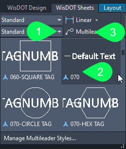
WisDOT Sheets tab > WisDOT Annotation console > Multileader way dropdown > Default Text 070
- WisDOT Sheets tab > WisDOT Annotation panel > Multileader
- MLEADER Specify leader arrowhead location or [leader Landing start Content starting time Options]: Click location of arrowhead at the benchmark location
- MLEADER Specify leader landing location: Select location for text
- Type Command Bespeak 28
- Check that text is in all CAPS. Right-click > All CAPS
- Click drag to expand text box
- Enter to add more lines of text
- Type additional lines of text as needed
- Click outside of the text box to end the command
- Type Command Bespeak 28
-
- Move multileader text to desired location
- Select the multileader text
- Select the upper left grip around the text and move the text to the desired location.
- Click to select new location
- Echo the procedure to depict additional benchmarks
- Final steps
- Double-Click outside the viewport
- Working in model space within the layout is deactivated
- Salve the file
- Double-Click outside the viewport
![]() Add benchmark table
Add benchmark table
pln-prod-pln-prof-13.mp4 4:54
- Steps to have before adding the benchmark tabular array if they take not been washed previously
- WisDOT Sheets tab > Standard Components panel > Add All Components
- Add together All Components will add all the WisDOT programme production elements (leader styles, dimension styles, etc.) that are not initially included in the WisDOT drawing template.
- 03 layout tab > Double-Click within the plan viewport
- Model space is activated within the viewport
- UCS
- UCS Specify origin of UCS or [Face NAmed OBject Previous View Earth X Y Z ZAxis]: 5 Enter
- WisDOT Sheets tab > Standard Components panel > Add All Components
- Insert the criterion table dynamic cake
- WisDOT Sheet tab > Sheets Cosmos console > Plan/Profile palette > PlanProfile palette tab > Blocks heading > Select Benchmark Table dynamic block
- EXECUTETOOL Specify insertion point or [Basepoint Scale X Y Z Rotate]: Click to place the block
- Block attribute editor
- If at that place is simply one criterion on the canvass
- type in the criterion aspect information
- if there is more than than one benchmark on the sheet
- OK
- If at that place is simply one criterion on the canvass
- select the benchmark table
- Click the visibility state downward pointing triangle
- Select how many benchmarks are on the sheet
- Esc
- WisDOT Sheet tab > Sheets Cosmos console > Plan/Profile palette > PlanProfile palette tab > Blocks heading > Select Benchmark Table dynamic block
- Enter benchmark information in the table
- Double Click on the benchmark tabular array
- Enhanced Attribute Editor dialog box is opened
- Select the Tag NO-1
- Value: 32
- Enter
- STA-1 value: 579+05.63 RT
- Enter
- ELEV-1 value: 1600.413
- Enter
- DESC-1 value: CP 27 0.75" Iron ROD SET WITH BLUE CAP
- Echo the process for addition benchmarks
- OK
- Enhanced Attribute Editor dialog box is opened
- Double Click on the benchmark tabular array
- Move the benchmark table to desired location
- Select the criterion tabular array
- Correct-click > Basic Modify Tools > Motion
- MOVE Specify base of operations point or [Displacement]: Click almost table to establish base point
- MOVE Specify 2d point: Motility table and Click at desired location
- Hide sheet information behind the criterion table
- WIPEOUT
- WIPEOUT Specify outset signal or [Frames Polyline]: Endpoint snap to the upper left corner of the table
- WIPEOUT Specify next point: Endpoint snap to the lower left corner of the tabular array
- WIPEOUT Specify next point or [Undo]: Endpoint snap to the lower right corner of the tabular array
- WIPEOUT Specify next point or [Close Disengage]: Endpoint snap to the upper right corner of the table
- Correct-click > Enter
- Select the table
- Turn on Selection Cycling if needed to help select the table cake
- Right-click > Display Social club > Bring to Forepart
- WIPEOUT
- Final steps
- Double-Click outside the viewport
- Working in model space inside the layout is deactivated
- Save the file
- Double-Click outside the viewport
![]() Add together sawcut line
Add together sawcut line
pln-prod-pln-prof-14.mp4 ii:01
- Steps to take before calculation the sawcut line if they have not been done previously
- WisDOT Sheets tab > Standard Components panel > Add together All Components
- Add together All Components volition add all the WisDOT plan production elements (leader styles, dimension styles, etc.) that are not initially included in the WisDOT cartoon template.
- 03 layout tab > Double-Click inside the plan viewport
- Model infinite is activated within the viewport
- WisDOT Sheets tab > Support panel > Toggle OsnapZ
-
OSNAPZ: ane

- Osnap substitutes the Z-value of the specified point with the acme set for the electric current UCS plane (Acme: 0)
-
- WisDOT Sheets tab > Standard Components panel > Add together All Components
- Add sawcut line
- Abode tab > Layers panel > Layer dropdown > speedily type P_R > scroll to and select P_RDWY_SawCutX
- Home tab > Draw console > Line dropdown > Create Line
- LINE Specify first point: Shift-correct-click Endpoint snap to the left side of the side route limits
- LINE Specify next point or [Undo]: Shift-correct-click Endpoint snap to the right side of the side route limits
- Enter
- REA Enter
- This may exist needed to regenerate the graphics displayed
- Repeat the process to describe additional sawcut lines
- Final steps
- (Optional) WisDOT Sheets tab > Support panel > Toggle OsnapZ
-
OSNAPZ: 0

- Osnap uses the Z-value of the specified bespeak
- This stride is only needed if i needs to snap to the actual elevation
-
- Double-click exterior the viewport
- Working in model infinite within the layout is deactivated
- Salve the file
- (Optional) WisDOT Sheets tab > Support panel > Toggle OsnapZ
![]() Add together cease construction multileader
Add together cease construction multileader
pln-prod-pln-prof-15.mp4 2:11
- Steps to take before calculation the construction multileader if they have not been done previously
- WisDOT Sheets tab > Standard Components panel > Add together All Components
- Add All Components will add together all the WisDOT program production elements (leader styles, dimension styles, etc.) that are not initially included in the WisDOT drawing template.
- 03 layout tab > Double-Click inside the plan viewport
- Model space is activated inside the viewport
- UCS
- UCS Specify origin of UCS or [Face NAmed OBject Previous View World X Y Z ZAxis]: V Enter
- WisDOT Sheets tab > Standard Components panel > Add together All Components
- Insert the "End Construction" multileader
- Dwelling house tab > Layers panel > Layer dropdown > quickly type P_R > whorl to and select P_MISC_Text
- WisDOT Sheet tab > Sheets Cosmos console > Plan/Profile palette > PlanProfile palette tab > Multileaders heading > Click Cease CONST STA MATCH multileader
- EXECUTETOOL Specify leader arrowhead location or [leader Landing first Content offset Options]:
- Shift right-click > Apparent Intersection snap
- Click the multileader arrow location at the intersection of the alignment and sawcut line
- EXECUTETOOL Specify leader landing location: Select location of text
- EXECUTETOOL Overwrite default text [Yes No]: No
- EXECUTETOOL Specify leader arrowhead location or [leader Landing first Content offset Options]:
- Alter the location of the structure multileader
- Select the multileader text
- Select the square grip at the upper left corner of the text
- Specify stretch point or [Base signal Copy Undo get out]: Click the location where the text will be moved to
- Esc
- Change the text of the construction multileader
- Double-click the text
- Click elevate to select the station information (Xxx+Twenty)
- Blazon 3+50
- Click exterior text box to end the edit
- Concluding steps
- Double-Click outside the viewport
- Working in model infinite within the layout is deactivated
- Save the file
- Double-Click outside the viewport
![]() Add multileader notes
Add multileader notes
pln-prod-pln-prof-xvi.mp4 3:30
- Steps to take before adding the multileader notes if they have not been done previously
- WisDOT Sheets tab > Standard Components panel > Add All Components
- Add All Components will add all the WisDOT plan product elements (leader styles, dimension styles, etc.) that are not initially included in the WisDOT drawing template.
- 03 layout tab > Double-Click inside the plan viewport
- Model infinite is activated inside the viewport
- UCS
- UCS Specify origin of UCS or [Face NAmed OBject Previous View World X Y Z ZAxis]: V
- WisDOT Sheets tab > Standard Components panel > Add All Components
- Insert circle tag multileader
- WisDOT Sheet tab > Sheets Cosmos console > Programme/Profile palette > PlanProfile palette tab > Set up Layer heading > Click P_MISC_Text
- WisDOT Sheets tab > WisDOT Annotation panel > Multileader style dropdown > 070-CIRCLETAG
- WisDOT Sheets tab > WisDOT Annotation panel > Multileader
- MLEADER Specify leader arrowhead location or [leader Landing outset Content get-go Options]: Click location of arrowhead location
- MLEADER Specify leader landing location: Click location of text
- Block attribute editor
- Enter tag number: ii
- OK
- Select the multileader> correct-click > Add Leader
- MLEADEREDIT Specify leader arrowhead location or [Remove leaders]: Select arrowhead location
- Right-click > Enter
- Identify slope intercept multileader
- WisDOT Sail tab > Sheets Creation console > Plan/Contour palette > PlanProfile palette tab > Multileaders heading > Click SI
- MLEADER Specify leader arrowhead location or [leader Landing showtime Content beginning Options]:
- Shift+right-click > Nearest snap Snap to the slope intercept line
- MLEADER Specify leader landing location: Click location of text
- EXECUTETOOL Overwrite default text [Yes No]: No
- MLEADER Specify leader arrowhead location or [leader Landing showtime Content beginning Options]:
- WisDOT Sail tab > Sheets Creation console > Plan/Contour palette > PlanProfile palette tab > Multileaders heading > Click SI
- Place existing right-of-way multileader
- WisDOT Sail tab > Sheets Creation panel > Plan/Contour palette > PlanProfile palette tab > Multileaders heading > Click EXISTING ROW
- MLEADER Specify leader arrowhead location or [leader Landing starting time Content kickoff Options]:
- Shift+correct-click > Nearest snap Snap to the existing right-of-way line
- MLEADER Specify leader landing location: Click location of text
- EXECUTETOOL Overwrite default text [Yes No]: No
- MLEADER Specify leader arrowhead location or [leader Landing starting time Content kickoff Options]:
- WisDOT Sail tab > Sheets Creation panel > Plan/Contour palette > PlanProfile palette tab > Multileaders heading > Click EXISTING ROW
- Place right-of-way multileader
- WisDOT Canvas tab > Sheets Creation panel > Plan/Profile palette > PlanProfile palette tab > Multileaders heading > Click ROW
- MLEADER Specify leader arrowhead location or [leader Landing starting time Content first Options]:
- Shift+correct-click > Nearest snap Snap to the right-of-way line
- MLEADER Specify leader landing location: Click location of text
- EXECUTETOOL Overwrite default text [Yes No]: No
- MLEADER Specify leader arrowhead location or [leader Landing starting time Content first Options]:
- WisDOT Canvas tab > Sheets Creation panel > Plan/Profile palette > PlanProfile palette tab > Multileaders heading > Click ROW
- Rotate and move multileader text
- Select the SI, EXISTING ROW and the ROW multileaders
- Right-click > Properties > Text heading
- Rotation: 0 Enter
- Select the square grip at the upper left corner of the multileader text
- Specify stretch betoken or [Base point Copy Disengage eXit]: Click the location where the text will be moved to
- Esc
- Multileaders are unselected
- Last steps
- Double-click outside the viewport
- Working in model space inside the layout is deactivated
- Save the file
- Double-click outside the viewport
![]() Add CAUTION cake
Add CAUTION cake
pln-prod-pln-prof-17.mp4 i:10
- Steps to have before adding the CAUTION block if they accept not been washed previously
- WisDOT Sheets tab > Standard Components panel > Add All Components
- Add All Components will add all the WisDOT program production elements (leader styles, dimension styles, etc.) that are not initially included in the WisDOT drawing template.
- 03 layout tab > Double-Click inside the plan viewport
- Model space is activated within the viewport
- UCS
- UCS Specify origin of UCS or [Face NAmed OBject Previous View World 10 Y Z ZAxis]: Five
- Home tab > Layers panel > Layer dropdown > quickly type P_M > scroll to and select P_MISC_Text
- WisDOT Sheets tab > Standard Components panel > Add All Components
- Insert Caution cake
- WisDOT Sheet tab > Sheets Creation panel > Plan/Profile palette > PlanProfile palette tab > Blocks heading > Select CAUTION block
- EXECUTETOOL Specify insertion point or [Basepoint Scale Ten Y Z Rotate]: Click to identify the cake
- WisDOT Sheets tab > WisDOT Annotation panel > Multileader style dropdown > Default Text 070
- WisDOT Sheets tab > WisDOT Annotation panel > Multileader
- MLEADER Specify leader arrowhead location or [leader Landing outset Content first Options]: Click location of arrowhead at the desired location
- MLEADER Specify leader landing location: Select location side by side to the Circumspection block
- Click outside the multileader
- Multileader is unselected
- WisDOT Sheet tab > Sheets Creation panel > Plan/Profile palette > PlanProfile palette tab > Blocks heading > Select CAUTION block
- Final steps
- Double-Click outside the viewport
- Working in model space within the layout is deactivated
- Relieve the file
- Double-Click outside the viewport
![]() Add text for utility names
Add text for utility names
pln-prod-pln-prof-18.mp4 2:fifteen
- Steps to take before adding the utility names if they accept not been washed previously
- WisDOT Sheets tab > Standard Components panel > Add All Components will add all the WisDOT programme production elements (leader styles, dimension styles, etc.) that are non initially included in the WisDOT drawing template.
- 03 layout tab > Double-Click inside the programme viewport Model space is activated within the viewport
- UCS Enter
- UCS Specify origin of UCS or [Face NAmed OBject Previous View Globe Ten Y Z ZAxis]: V Enter
- Home tab > Layers console > Layer dropdown > chop-chop type P_M > scroll to and select P_MISC_Text
- Insert multiline text
- WisDOT Sheets tab > WisDOT Annotation console dropdown > Set WisDOT Textstyle/Size
- WisDOT Annotate dialog box
- Font type: CalibriLight
- Font height: 0.070
- Open Annotate Ribbon
- WisDOT Annotate dialog box
- Annotate tab > Text panel > Multiline Text
- MTEXT Specify offset corner: Click kickoff corner at the acme left
- MTEXT Specify contrary corner or [Height Justify Line spacing Rotation Style Width Columns]: Click opposite corner at the bottom right
- MTEXT:
- type the name of the utility company
- Enter
- Enter
- Enter
- Click outside the multiline text box
- Select the multiline text > right-click > Basic Modify Tools > Copy
- Re-create Specify base point or [Displacement mOde]: Click near text
- F8 to plow on ORTHOMODE
- Copy Specify second point or [Array]: Click location for copied text
- Esc
- Double Click copied text
- Edit copied text
- Esc
- WisDOT Sheets tab > WisDOT Annotation console dropdown > Set WisDOT Textstyle/Size
![]() Create and edit utility legend
Create and edit utility legend
pln-prod-pln-prof-19.mp4 5:26
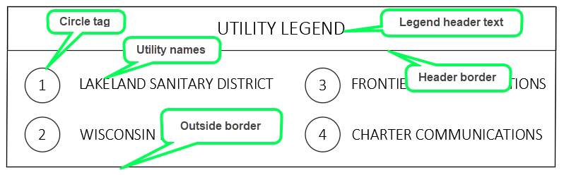
- Create fable header text
- WisDOT Sheets tab > WisDOT Annotation console dropdown > Set WisDOT Textstyle/Size
- WisDOT Comment dialog box
- Font type: CalibriLight
- Font top: 0.0875
- Open Comment Ribbon
- WisDOT Comment dialog box
- Annotate tab > Text console > Multiline Text
- MTEXT Specify first corner: Click first corner at the height left
- MTEXT Specify reverse corner or [Pinnacle Justify Line spacing Rotation Style Width Columns]: Click opposite corner at the bottom right
- MTEXT: type UTILITY LEGENDClick
- Click exterior the multiline text
- Select the multiline text > right-click > Justify
- JUSTIFYTEXT [Left Marshal Fit Center Middle Right TL TC TR ML MC MR BL BC BR]: MC
- WisDOT Sheets tab > WisDOT Annotation console dropdown > Set WisDOT Textstyle/Size
- Create exterior border of legend table
- Dwelling house tab > Draw panel > Rectangle
- RECTANG Specify outset corner point [Chamfer Top Fillet Thickness Width]: Click first corner at the top left
- RECTANG Specify other corner indicate or [Area Dimensions Rotation]: Click reverse corner at the bottom right
- Adjust the shape of the edge using the grips
- Dwelling house tab > Draw panel > Rectangle
- Create fable header border
- Home tab > Describe panel > Rectangle
- RECTANG Specify kickoff corner point [Chamfer Elevation Fillet Thickness Width]:
- Shift+right-click > Endpoint Snap at the top left corner of the outside legend border
- RECTANG Specify other corner point or [Surface area Dimensions Rotation]:
- Shift+right-click > Nearest Snap the contrary corner along the right side of the outside edge
- RECTANG Specify kickoff corner point [Chamfer Elevation Fillet Thickness Width]:
- Home tab > Describe panel > Rectangle
- Eye tabular array header text
- Select header text UTILITY LEGEND
- Select the middle center grip of text
- Specify stretch point or [Base point Copy Disengage eXit]:
- Shift+right-click > Mid Between 2 Points
- Showtime point of mid:
- Shift+right-click > Midpoint
- mid of: Snap to the left side of the legend header rectangle
- Shift+right-click > Midpoint
- 2d indicate of mid:
- Shift correct-click > Midpoint
- mid of: Snap to the right side of the fable header rectangle
- Shift correct-click > Midpoint
- Showtime point of mid:
- Shift+right-click > Mid Between 2 Points
- Specify stretch point or [Base point Copy Disengage eXit]:
- Esc
- Insert circle tag
- WisDOT Sheets tab > WisDOT Annotation console > Multileader style dropdown > 070-CIRCLETAG
- WisDOT Sheets tab > WisDOT Annotation panel > Multileader
- MLEADER Specify leader arrowhead location or [leader Landing first Content first Options]: Click location of arrowhead location
- F8 to turn off ORTHOMODE if needed
- MLEADER Specify leader landing location: Click location of text to the left of the utility proper noun
- Block attribute editor
- Enter tag number: 1
- OK
- Select the multileader > right-click > Remove Leader
- MLEADEREDIT Specify leaders to remove or [Add together leaders]: Select the multileader
- Enter
- Select the circle tag > right-click > Basic Modify Tools > Move
- MOVE Specify base point or [Displacement]: Click location near circumvolve tag
- Move Specify second bespeak or < use first point as deportation >: Click to move circle tag to desired location
- MLEADER Specify leader arrowhead location or [leader Landing first Content first Options]: Click location of arrowhead location
- Duplicate circle tags
- CO Enter
- Re-create Select objects: Select circle tag in the fable
- Enter
- Re-create Specify base of operations indicate or [Displacement style]: Click location near circle tag to be copied
- F8 to plough on ORTHOMODE
- COPY Specify 2d indicate or [Assortment Exit Undo]: Click at the location where the copied circle tags will be placed
- Enter
- Re-create Select objects: Select circle tag in the fable
- Repeat the process as many times as needed 3. Multiple circle tags can be copied at the aforementioned fourth dimension
- CO Enter
- Update numbers within circle tags
- Double-click the circumvolve tag
- Cake attribute editor
- Enter tag number: 2
- OK
- Cake attribute editor
- Echo the process as many times as needed
- Double-click the circumvolve tag
- Hibernate sheet data backside the legend table
- WIPEOUT Enter
- WIPEOUT Specify offset betoken or [Frames Polyline]: Endpoint snap to the upper left corner of the table
- WIPEOUT Specify next point: Endpoint snap to the lower left corner of the table
- WIPEOUT Specify adjacent point or [Undo]: Endpoint snap to the lower correct corner of the table
- WIPEOUT Specify side by side point or [Close Undo]: Endpoint snap to the upper right corner of the table
- Right-click > Enter
- Select the Wipeout >correct-click > Display Order > Bring Higher up Object
Turn on Pick Cycling if needed to aid select the wipeout
- Select reference objects: Select XREF data and additional sheet data that should not announced within the legend table
- Enter
- REA Enter This may be needed to regenerate the graphics
- WIPEOUT Enter
- Final steps
- Double-Click outside the viewport
- Working in model infinite within the layout is deactivated
- Save the file
- Double-Click outside the viewport
![]() Add and label ditch profiles, cross pipe, and flow arrows
Add and label ditch profiles, cross pipe, and flow arrows
pln-prod-pln-prof-xx.mp4 5:sixteen
Initial steps
Steps to take before adding ditch profile labels, cross pipes and flow arrows if they accept non been done previously
- WisDOT Sheets tab > Standard Components console > Add together All Components
- Add All Components will add together all the WisDOT programme production elements (leader styles, dimension styles, etc.) that are not initially included in the WisDOT drawing template.
- 03 layout tab > Double-Click within the programme or profile viewport
- Model space is activated within the viewport
- UCS (when working in plan viewport)
- UCS Specify origin of UCS or [Face NAmed OBject Previous View World X Y Z ZAxis]: V
Add together ditch profiles
- Dwelling house tab > Layers panel > Layer dropdown > apace blazon P_M > curl to and select P_MISC_Text
- Toolspace palette > Prospector tab > Data Shortcuts > Alignments > Centerline Alignments > 51 > Profiles > Right-click 51-Ditch-LT > Create Reference
- Create Contour Reference dialog box
- Profile style: PROF Ditch Flow Line
- Contour label set: _No Labels
- OK
- Create Contour Reference dialog box
- Repeat the process for the 51-Ditch-RT profile
- Add multileader text to label correct ditch profile
- WisDOT Sheets tab > WisDOT Annotation panel > Multileader style dropdown > Default Text 070
- WisDOT Sheets tab > WisDOT Note panel > Multileader
- MLEADER Specify leader arrowhead location or [leader Landing beginning Content outset Options]: Click location along the ditch contour
- MLEADER Specify leader landing location: Click location of text
- Type DITCH PROFILE RIGHT
- Check that text is in all CAPS
- Correct-click > All CAPS
- Select exterior of the text box to stop the command
- Check that text is in all CAPS
- Type DITCH PROFILE RIGHT
- Alternate label method: begin with PROPOSED PROFILE multileader to characterization left ditch
- WisDOT Sheet tab > Sheets Cosmos panel > Plan/Profile palette > PlanProfile palette tab > Multileaders heading > Click PROPOSED Profile
- MLEADER Specify leader arrowhead location or [leader Landing outset Content first Options]:
- Shift+right-click > Nearest snap
- Snap to the ditch profile
- MLEADER Specify leader landing location: Click location of text
- EXECUTETOOL Overwrite default text [Yeah No]: Yeah
- Type DITCH PROFILE LEFT
- Select outside of the text box to end the control
- MLEADER Specify leader arrowhead location or [leader Landing outset Content first Options]:
- WisDOT Sheet tab > Sheets Cosmos panel > Plan/Profile palette > PlanProfile palette tab > Multileaders heading > Click PROPOSED Profile
Add canal pipes in profile view
- Home tab > Layers panel > Layer dropdown > quickly blazon P_P > scroll to and select P_PROF_Culvert
- Select the profile filigree
- Profile View Contextual ribbon > Modify View console > Profile View Properties
- Profile View Properties dialog box
- Pipe Network tab
- Unselect to draw the structures
- Unselect the 582+50B culvert pipage
- OK
- Esc
- Pipe Network tab
- Profile View Properties dialog box
Add flow arrows
- Home tab > Layers console > Layer dropdown > rapidly type P_E > scroll to and select P_EC_FlowArrow
- WisDOT Sheets tab > Sheets Cosmos panel > Structure Details dropdown > Drainage and Utilities palette > Erosion Command tab > Blocks heading > Click EC Menstruation Pointer
- EXECUTETOOL Specify insertion bespeak or [Basepoint Scale Ten Y Z Rotate]: Select location for period arrow
- EXECUTETOOL Specify rotation angle: Click orientation of flow arrow
- Alter orientation of flow pointer
- Select the flow pointer
- Select circular grip
- Specify rotation angle or [Base bespeak Undo go out]: Click orientation of flow arrow
- Esc
- Add additional flow arrows as needed.
Final steps
- Double-Click outside the viewport
- Working in model space within the layout is deactivated
-
Save the file
Exercise files: pln-prod-pln-prof-finish-information-c3d20.zilch
Back to acme
Source: https://c3dkb.dot.wi.gov/Content/c3d/pln-prod/pln-prod-pln-prof.htm
Post a Comment for "I 15 Road Plan and Profile Drawings"